
Check also previous article why I chose DS9490R and DS18B20 in here.
At first I created simple connection board and connected sensors as simple star and used parasitic power – power was delivered using the same cable what was used for data transfer. That idea resulted with lots of anomalies and in some point I was not even able to see more than 4 sensors at the time. So it was back to the books.
After reading guidelines for reliable long line 1-wire networks I created new powered hub, got rid of parasitic power and added 150ohm resistors to data lines to minimize reflections. In general, schematic looked like on picture below. Connecting sensors with RJ12 plugs-sockets are optional. You may solder sensor wires together or connect with breadboard.
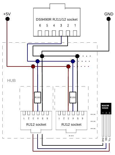
Connecting DS9490R with DS18B20 sensors
I wanted to remind myself how to create PCB at home and spent couple of days to make hub with 15 RJ12 sockets so that I could easily plug and unplug different 1-wire sensors. I used special “Press-n-peel” blue film, created schematics in KiCad program etc. When I have time I will put that part also somewhere here.
If you found this useful, say thanks, click on some banners or donate, I can always use some beer money.
Next – How to get DS9490R adapter and DS18B20 sensors working.